A filter selection mistake costs far more than a coupler mistake. Get a coupler wrong and you lose a fraction of a dB in insertion loss. Get a filter wrong and you can burn out a power amplifier, eat the entire link budget with in-band insertion loss, or watch the center frequency drift out of band at high temperature.
The most common mistake in selection guides is asking "which filter is best." No single technology wins on every dimension. The four technology routes each occupy a different region of power handling, insertion loss, Q factor, size, and temperature stability. Selection is finding the intersection of five hard constraints, not finding an "optimal solution."
This article breaks down the real engineering boundaries of the four filter types in DAS and RF systems, with a comparison table you can take directly into a decision.
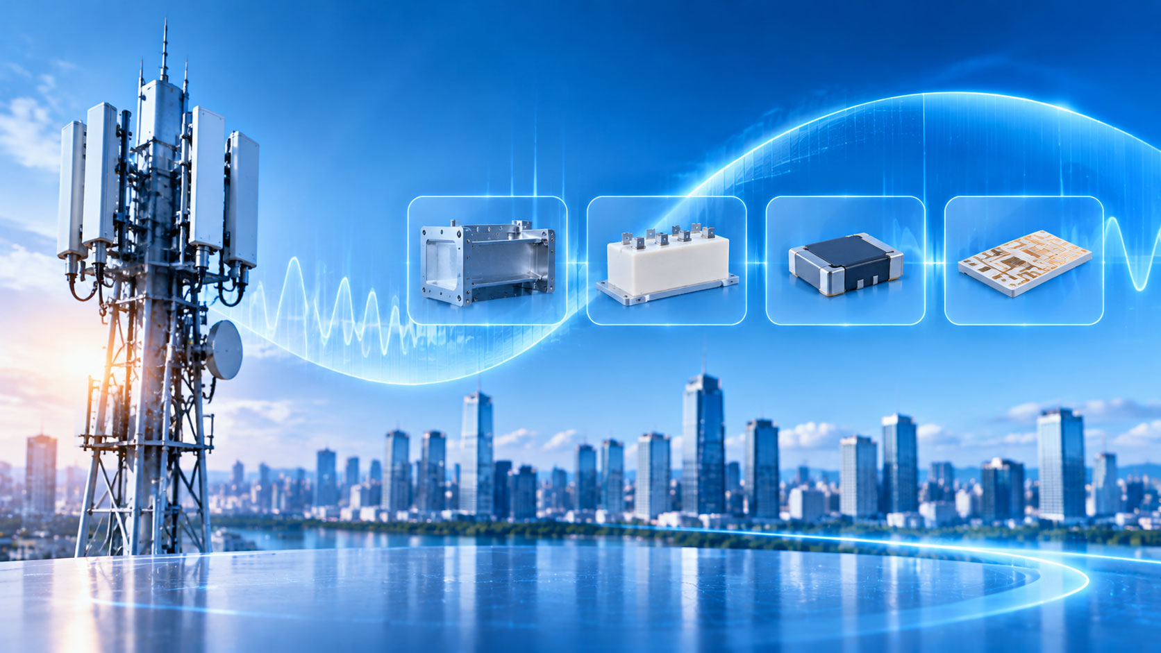
What Each of the Four Filters Actually Covers
Draw the technology boundaries first, then talk about specific parameters.
Cavity Filter
A cavity filter is essentially a set of metal resonant cavities connected by coupling windows. Q factor is in the 2,000 to 10,000 range, with some designs going higher. High Q means extremely low insertion loss (within 0.2dB) and very steep roll-off. Power handling is 50W to 500W continuous wave, with high-power models reaching 200W CW / 1500W peak. The trade-off is size. A conventional coaxial cavity filter at 2GHz is roughly fist-sized (80×60×40mm), and cost is high — custom parts can run into thousands of dollars.
Dielectric Filter
A dielectric filter uses high-permittivity ceramic resonators — essentially shrinking the cavity into ceramic. Q factor is in the hundreds to low thousands, an order of magnitude below cavity but far higher than LC and microstrip. Size is much smaller than a cavity at the same frequency. Temperature-compensated ceramic can hold frequency drift to ±3ppm/°C or even ±1ppm/°C. Power handling is medium; ceramic dielectric filters typically top out around 5W input, while dielectric waveguide structures can go higher. In recent years, 5G Massive MIMO has adopted dielectric filters heavily: every channel needs filtering, cavity won't fit, LC performance isn't enough, and dielectric lands right in between.
SAW Filter
A SAW filter uses acoustic wave resonance on the surface of a piezoelectric material. Q is high (SAW typically in the thousands to 10,000+), size is extremely small (0805 capacitor size), roll-off is very steep, and it suits wafer-level high-volume production. But power capability is a hard boundary. Continuous wave power above 2W, or peak above 33dBm, risks destroying a SAW. Typical bandpass SAW insertion loss is 1–2dB or more, with some products reaching 2.4–3.0dB. Frequency coverage is roughly 100MHz to 2–3GHz; above that, SAW loss and size both become unfavorable.
Microstrip Filter
A microstrip filter is a planar process with conductors etched on a dielectric substrate. Cost is lowest, size is small, design is flexible, but Q is limited (LC/microstrip level), insertion loss is typically 1–6dB, and power capability is also limited. The biggest pitfall with microstrip is not electrical — it's temperature stability: a microstrip filter on FR4 can drift at -100 to -300ppm/°C, because FR4's permittivity changes dramatically with temperature. Rogers PTFE substrates are better (±50–100ppm/°C), and alumina substrates can reach ±30ppm/°C, but cost and process complexity rise accordingly.
Five Hard Constraints in One Table
|
Dimension
|
Cavity
|
Dielectric
|
SAW
|
Microstrip (FR4)
|
|
Q factor
|
2,000–10,000+
|
Hundreds to low thousands
|
Thousands to 10,000+
|
Low (LC level)
|
|
Insertion loss
|
Within 0.2dB
|
Low to medium (<1dB common)
|
1–3dB
|
1–6dB
|
|
Power handling (CW)
|
50W–500W+
|
~5W (dielectric waveguide higher)
|
<2W
|
Low to medium
|
|
Temperature drift
|
-3 to -5ppm/°C (aluminum cavity)
|
±3ppm/°C (compensated ceramic)
|
Tens of ppm/°C (standard SAW)
|
-100 to -300ppm/°C (FR4)
|
|
Size
|
Large (fist-sized at 2GHz)
|
Medium (much smaller than cavity)
|
Extremely small (0805 class)
|
Small (PCB area)
|
|
Cost
|
High
|
Medium
|
Low (high volume)
|
Lowest
|
The two most striking numbers in this table: SAW's 2W power ceiling, and FR4 microstrip's -100 to -300ppm/°C drift. These are not "slightly worse performance" — they are "use it in the wrong scenario and it fails outright."
DAS Selection Logic: Eliminate the Impossible First, Then Compare What's Left
The power and reliability requirements of a DAS naturally divide the four filter types into different "usable zones."
Step 1: Look at power.
Continuous wave power at the DAS backbone and source output is typically in the 20W to 100W range, higher in some macro scenarios. SAW's 2W ceiling eliminates it immediately. Microstrip filter power capability is below tens of watts and doesn't hold up on a high-power backbone either. Cavity and dielectric remain.
Step 2: Look at the insertion loss budget.
In a DAS link budget, every stage of component insertion loss is amplified by downstream attenuation. Cavity's insertion loss within 0.2dB has a clear advantage in long links. Dielectric insertion loss is slightly higher but still acceptable, depending on the specific band and bandwidth design.
Step 3: Weigh temperature and size.
If the equipment is installed in a temperature-controlled cabinet (indoor DAS equipment room), cavity's size and cost are acceptable — choose cavity first for maximum margin in insertion loss and power. For 5G Massive MIMO, where channels are dense and every channel needs filtering, cavity won't fit; the size-performance compromise of dielectric filters becomes irreplaceable. Dielectric temperature drift with compensated ceramic can reach ±3ppm/°C or better, sufficient for most indoor environments.
Do SAW and microstrip have a place in DAS?
Yes, but not on the power path. SAW suits receiver front-end filtering — signal levels are low, power isn't an issue, and what's needed is very steep roll-off and extremely small size. Microstrip suits low-power, narrowband, cost-sensitive, temperature-controlled auxiliary filtering nodes. If a DAS branch needs simple harmonic suppression or spurious rejection, microstrip is the lowest-cost option — provided the substrate material is chosen correctly. FR4 in a temperature-varying environment will let the filter center frequency "walk away."
The Pitfalls That Catch People Most Often
Pitfall 1: Looking only at insertion loss, ignoring Q and bandwidth.
Cavity filters have low insertion loss because high Q allows narrowband design while keeping loss low. Force a cavity into a wide band and the Q advantage is diluted, insertion loss rises, and the size advantage disappears. Dielectric Q is sufficient for medium bandwidth, but if the requirement is very narrowband (relative bandwidth <1%), dielectric Q may not be enough and roll-off won't be steep. Narrowband high rejection → cavity. Medium bandwidth, size-constrained → dielectric. This matching relationship matters more than comparing insertion loss numbers alone.
Pitfall 2: Ignoring the substrate temperature characteristics of microstrip filters.
FR4's -100 to -300ppm/°C is not an "extreme condition" — it's a typical value near room temperature. A microstrip filter operating at 2GHz with 50MHz bandwidth can drift 10–15MHz over a 50°C temperature change — 20–30% of the bandwidth. If there isn't enough guard band in front of the filter, in-band insertion loss rises sharply. Using an FR4 microstrip filter in an environment with more than ±20°C variation requires temperature compensation or a different substrate.
Pitfall 3: SAW power ceiling masked by "average."
SAW power limits are usually specified as continuous wave or average power, but real signals have peak-to-average ratio (PAPR). A signal with 1W average power and 8dB PAPR has nearly 6W peak power — far beyond SAW's capability. When using SAW on a path with modulated signals, judge safety by peak power, not average power.
Pitfall 4: Dielectric temperature coefficient must be read as "compensated."
"Dielectric filters have good temperature stability" needs a qualifier. Standard communication-grade dielectric materials drift ±10–30ppm/°C. Only high-end products using temperature-compensated ceramic achieve within ±3ppm/°C. If you assume "dielectric filter" means temperature-stable without checking, you may get a standard-grade part that differs from expectations by several times in wide-temperature scenarios.
Maniron's Coverage in the Filter Category
Maniron's RF passive component line is built around cavity structures, covering 340MHz to 7125MHz, with PIM as low as -161dBc. In the power-insertion loss-temperature stability triangle of DAS backbone and source output, cavity filters are the choice with the fewest constraints. Dielectric-loaded cavity designs can reduce size while maintaining cavity performance, suitable for space-constrained DAS nodes.
For low-power auxiliary scenarios that would use SAW or microstrip, Maniron does not directly cover every technology route, but the low insertion loss and low PIM of cavity filters make them the most reliable replacement for SAW and microstrip on the DAS power path. Each device comes with an individual test report including insertion loss, VSWR, and PIM measured data, with lot-level traceability.