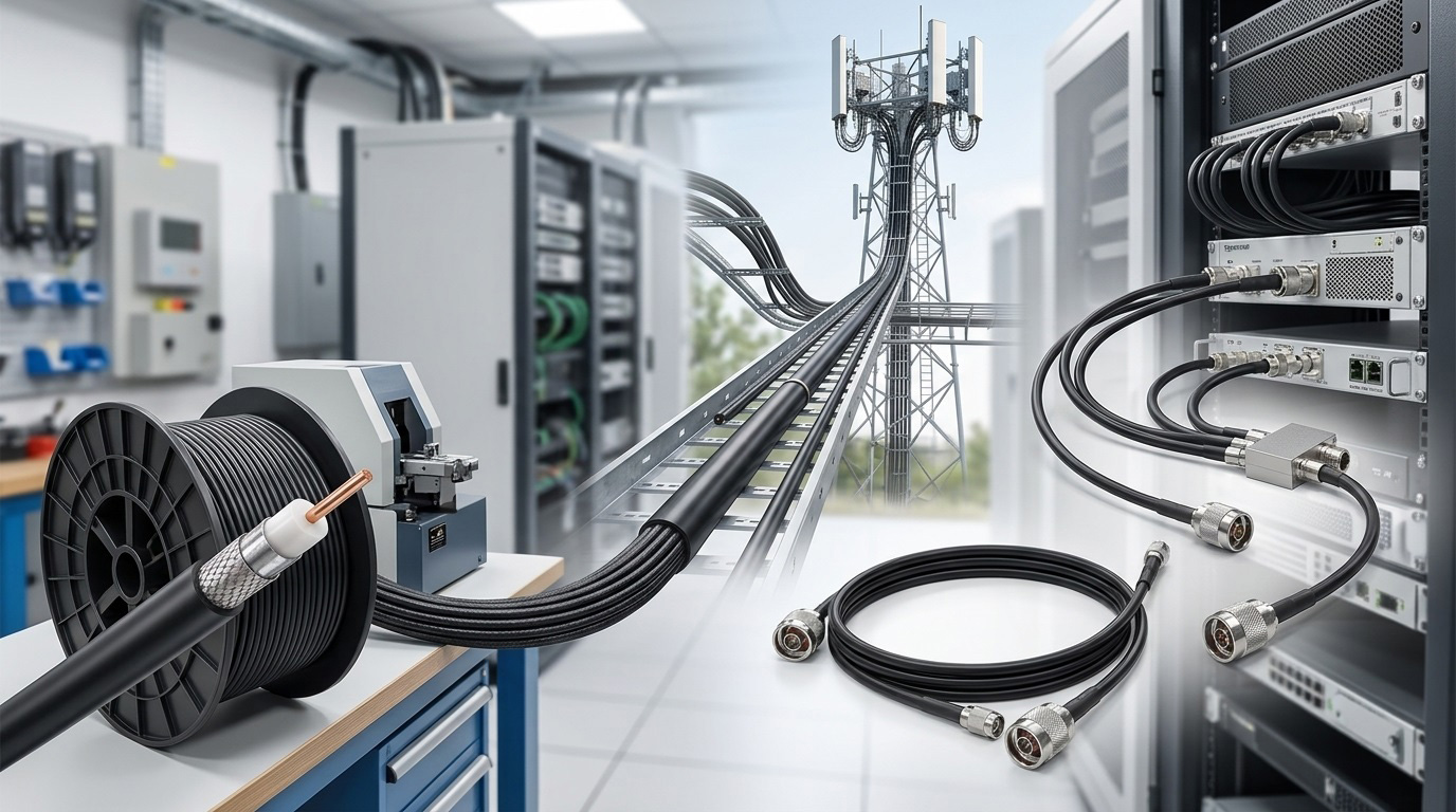
These three concepts do not sit on the same logical plane.
Cable is a material‑level generic term — any coaxial cable that carries RF signals, whether semi‑rigid, semi‑flexible, or braided, is called a cable.
Feeder and jumper are functional‑level classifications — both are specific application forms of cable, distinguished by the role they play in the system.
In one sentence: a feeder is the highway, a jumper is the interface, and cable is the physical medium for both.
Definitions: What Each Concept Covers
Cable
Cable is the general term for RF coaxial cable. A coaxial cable consists of an inner conductor, a dielectric layer, a shield, and an outer jacket. The inner conductor carries the signal, the shield provides both conduction and shielding (the metal shield should be grounded when in use), the dielectric determines the high‑frequency loss characteristics, and the outer jacket provides mechanical protection and moisture resistance.
Coaxial cable types include: RG series, corrugated copper tube series, semi‑steel semi‑flex series, low‑loss series, etc. Structurally, they can be classified by flexibility into semi‑rigid, semi‑flexible, and braided types.
Key point: cable is a "material", not a "use". The same cable used on an antenna tower is called a feeder; used inside an equipment cabinet it is called a jumper. The cable itself does not determine its functional role.
Feeder
A feeder is the RF transmission line connecting the antenna to the transceiver.
The engineering definition of a feeder has three qualifying conditions:
First, long transmission distance. A feeder typically runs from the equipment room all the way to the antenna on the tower, with lengths ranging from tens of meters to over a hundred meters. In China Telecom's 2019 feeder procurement project, a single purchase reached 120,000 kilometers — this figure itself indicates the typical length scale of feeders.
Second, low transmission loss. The main task of a feeder is to deliver the signal power from the transmitter output to the antenna input with minimal loss. This means feeders must use low‑loss cable structures — usually corrugated copper tube or foam dielectric braided cable.
Third, relatively large physical size. Common feeder sizes include 1/2 inch, 7/8 inch, 1‑5/8 inch, etc. The larger the size, the lower the attenuation per unit length.
Jumper
A jumper is a cable assembly with RF connectors on both ends, used for short‑distance connections between equipment or between equipment and feeder.
The engineering definition of a jumper has three qualifying conditions:
First, both ends must have connectors. A jumper is not bare cable; it is a cable assembly — the cable ends are already soldered or crimped with RF connectors (N‑type, 4.3‑10, 7‑16 DIN, etc.). This is the most intuitive difference from ordinary cable.
Second, short connection distance. Jumpers are used for connections between equipment, between equipment and feeder, and between components. Typical lengths range from 0.5 meters to 3 meters.
Third, must be flexible. Jumpers need to be bent and routed in tight spaces such as equipment cabinets and antenna ports, so they require small bend radius and good flexibility. Super flexible cable is commonly used, such as 1/2 inch super flexible jumper.
Comparison: One Table to Clarify the Differences
|
Aspect
|
Cable
|
Feeder
|
Jumper
|
|
Concept level
|
Material generic
|
Functional classification
|
Functional classification
|
|
Essence
|
General term for coaxial cable
|
Main transmission line between antenna and equipment
|
Short connection assembly with connectors on both ends
|
|
Typical length
|
Unlimited
|
Tens to hundreds of meters
|
0.5 m to 3 m
|
|
Typical size
|
1/4" to 1-5/8"
|
7/8", 1/2"
|
1/2", 3/8", 1/4"
|
|
Flexibility
|
Depends on type
|
Lower (fixed routing)
|
High (bending in tight spaces)
|
|
Loss requirement
|
Depends on use
|
Extremely low (long distance)
|
Low (short distance)
|
|
Typical structure
|
Semi‑rigid / semi‑flex / braided
|
Corrugated copper, foam dielectric
|
Super flexible braided, semi‑flexible
|
|
Connectors included
|
No
|
No (field installed)
|
Yes (factory pre‑assembled)
|
|
Typical application
|
All RF transmission scenarios
|
Base station antenna feeder, DAS backbone
|
Inter‑equipment, feeder‑to‑antenna
|
Engineering Intuition: Why Can't One Cable Do It All?
If we look only at electrical performance, a sufficiently thick feeder could meet both long‑distance transmission and short‑distance connection needs. Why does engineering practice still distinguish between feeder and jumper?
The reason is not electrical — it is mechanical.
The core constraint of a feeder is attenuation. Coaxial cable attenuation is proportional to the square root of frequency and inversely proportional to cable diameter. At 2.6GHz, a 1/2‑inch braided cable has about 7‑8dB loss per 100 meters; a 7/8‑inch corrugated copper cable has about 4‑5dB loss per 100 meters. For a 100‑meter tower‑to‑equipment‑room distance, using 1/2‑inch cable means the signal loses 7‑8dB before reaching the antenna — equivalent to an 80% reduction in transmit power. Therefore, long‑distance transmission must use large‑diameter, low‑loss feeders.
The core constraint of a jumper is bend radius. The space at the antenna port is extremely limited, and the routing space inside equipment cabinets is even tighter. The minimum bend radius of a 7/8‑inch feeder is typically over 200mm, making it impossible to install at equipment ports. A 1/2‑inch super flexible jumper can achieve a minimum bend radius of less than 50mm, allowing connection in tight spaces.
In other words: feeders sacrifice flexibility for low loss; jumpers sacrifice low loss for flexibility. In the same system, both needs exist simultaneously, so different cables must be used to satisfy them.
Application Scenarios: Roles in a DAS System
Taking a typical indoor distribution system as an example, the signal path from source to antenna uses three types of cable as follows:
Source output → Jumper → Combiner/Splitter → Jumper → Main feeder → Jumper → Antenna
-
Jumper handles all short‑distance transitions between equipment: source to combiner, combiner to splitter, splitter to feeder, feeder to antenna. Each connection requires a jumper.
-
Feeder handles long‑distance backbone transmission between floors or from equipment room to antenna. In tunnel scenarios, the feeder may run continuously for hundreds of meters.
-
Cable is the physical material carrier for all the above connections.
In Maniron's RF passive component product line, combiners, splitters, couplers, and other components are equipped with standard connector interfaces (N‑type, 4.3‑10, etc.). This means that during system integration, a matching jumper assembly is required between each component and the next. The PIM performance and VSWR of the jumper directly affect the noise floor and VSWR of the entire link — PIM introduced by a poor‑quality jumper can undo all the investment in low‑PIM components upstream.
Selection Guide
Feeder selection – three numbers matter: frequency, length, attenuation budget. Below 2.6GHz and within 100 meters, 1/2‑inch feeder is usually sufficient; beyond 100 meters or at higher frequencies, consider 7/8‑inch.
Jumper selection – three numbers matter: bend radius, connector type, PIM specification. Bend radius determines whether it can be installed; connector type determines whether it can be mated; PIM specification determines whether the system noise floor will be raised after installation.
Cable selection – look at the application environment: for outdoor use, corrugated copper tube or waterproof braided cable; for indoor use, ordinary braided cable is sufficient.
FAQ
Q1: Can a feeder and a jumper be used interchangeably?
In principle, no. A feeder is too stiff to bend at equipment ports; a jumper is too thin and has excessive loss over long distances. However, in short‑distance, low‑loss scenarios (e.g., inter‑equipment connections within 3 meters), using a thin feeder instead of a jumper is feasible.
Q2: Why must a jumper have connectors on both ends?
By definition, a jumper is a "cable assembly" — the cable ends are already soldered or crimped with connectors at the factory. Installing connectors on bare cable on site is what you do with a feeder.
Q3: In a DAS, which has more impact on PIM — jumper or feeder?
Both matter, but jumpers are the more common PIM source. Because jumpers are repeatedly bent and re‑torqued, the mechanical stability at the connector is more easily compromised. A jumper that has been repeatedly disconnected and reconnected can degrade from -160dBc to -130dBc.
Q4: What is the difference between a 1/2‑inch super flexible jumper and a 1/2‑inch feeder?
Same size, different construction. The super flexible jumper uses a finer braided inner conductor and softer dielectric material, achieving a smaller minimum bend radius, but with slightly higher loss per unit length than a standard feeder of the same size.
Q5: What are the grounding requirements for the cable shield?
The metal shield should be grounded when in use. Failure to ground or poor grounding reduces shielding effectiveness and allows external interference to couple into the cable.