
What It Is
A combiner is an RF device that merges multiple RF signals into a single output, typically featuring two or more input ports and one output port. A duplexer is a three‑port RF device that isolates transmit and receive signals, enabling them to share a single antenna.
How It Works
A combiner uses cavity resonators and circulators, utilizing filtering and unidirectional conduction to synthesize multiple signals into one path. A duplexer consists of two sets of band‑pass filters (transmit and receive filters) operating at different frequencies, achieving simultaneous transmit/receive operation through frequency‑domain isolation.
Why It Matters
Combiners conserve antenna and feeder resources, simplifying system cabling. Duplexers are essential for single‑antenna two‑way communication (full‑duplex operation). Incorrect selection leads to increased signal attenuation (3dB hybrid combiners have a theoretical 3dB loss), mutual interference, and even receiver damage.
A combiner is an RF device that combines two or more RF signals from different transmitters into a single output path for transmission via a single antenna, while preventing mutual interference between the input ports. A combiner generally has multiple input ports and only one output port.
Core specifications for a combiner include:
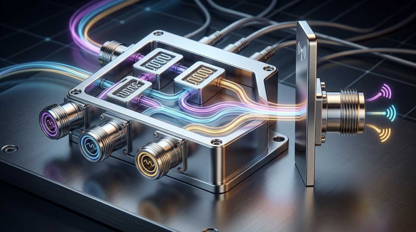
A duplexer is a three‑port RF device that integrates the uplink and downlink paths into a single module, isolating the transmit and receive signals to ensure simultaneous operation without interference. It consists of two sets of band‑pass (or band‑stop) filters tuned to different frequencies, with the common port connected to the antenna.
Core specifications for a duplexer include:
A combiner is composed of cavity resonators and circulators:
Critical Physical Principle: For non‑frequency‑selective combiners (e.g., 3dB hybrids), combining introduces a theoretical 3dB loss. When two equal‑power signals are combined and only one output port is used (with the other terminated), half the power (3dB) is lost. Frequency‑selective combiners can achieve lower losses using the band‑pass characteristics of filters.
Duplexer operation is based on Frequency Division Duplexing (FDD), where transmit and receive use different frequencies:
Critical Difference: The two signal paths in a duplexer flow in opposite directions (one transmit, one receive), whereas all signal paths in a combiner flow in the same direction (all for transmission).
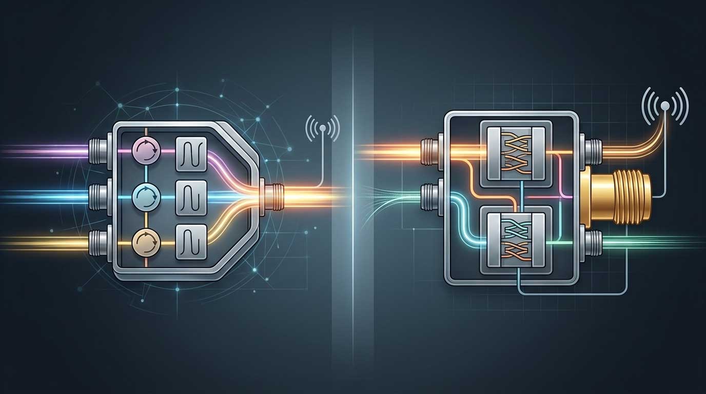
Core Conclusion: Combiners solve the problem of "how multiple signals share a single transmission path." Duplexers solve the problem of "how transmit and receive signals share a single antenna without interfering with each other." They are not interchangeable.
First, determine whether the requirement is "multi‑transmitter signal combining" or "single‑antenna Tx/Rx sharing." Multiple transmitters sharing an antenna → Choose a Combiner. Single‑antenna two‑way communication → Choose a Duplexer.
Confirm whether the system impedance is 50Ω or 75Ω and ensure the combiner/duplexer matches the system impedance. Impedance mismatch leads to increased VSWR and reflected power.
The most common misconception is assuming the two are functionally identical and interchangeable. In reality, combiners lack the Tx/Rx isolation functionality of duplexers. Using a combiner in a shared‑antenna Tx/Rx scenario allows transmit power to leak directly into the receive channel — at best causing receiver desensitization/blocking, and at worst burning out the receiver front‑end.
Non‑selective combiners (e.g., 3dB hybrids) have an inherent theoretical 3dB loss, whereas frequency‑selective combiners achieve much lower losses through filter passband characteristics. Incorrectly selecting a non‑selective combiner in low‑loss scenarios wastes half the transmit power.
The Tx and Rx ports on a duplexer are specifically tuned for their respective frequencies. If the transmitter is connected to the Rx port and the receiver to the Tx port, the system will not function correctly. The passband mismatch causes high VSWR, and the reflected power can damage the transmitter.
The cavity resonators in combiners can drift with temperature changes. The typical aging drift is <3ppm per year. In outdoor or high‑temperature‑variation environments, failure to account for temperature compensation can cause the combiner to drift off its design frequency, leading to a sharp increase in insertion loss.
Q1: Are combiner and duplexer actually the same thing?
No, they are not. A combiner merges multiple RF signals into a single output path, with all signals flowing in the same direction, primarily for transmit‑side power combining. A duplexer is a three‑port device that isolates transmit and receive signals to enable single‑antenna two‑way communication, with signal paths flowing in opposite directions. The two devices differ fundamentally in function, signal flow, internal structure, and key specifications, and should never be used interchangeably.
Q2: Do combiners have frequency‑selection capability?
It depends on the type. Non‑selective combiners (e.g., 3dB hybrids) do not have frequency selection. Selective combiners do have frequency selection capability; their principle and design are identical to duplexers — they are combinations of filters tuned to different bands. Selective combiners can combine multiple transmit signals within the same band or across different bands.
Q3: Can a combiner and a duplexer be used as substitutes for each other?
Generally, no. Under specific conditions, a combiner can function as a duplexer (for single‑antenna Tx/Rx sharing, provided isolation requirements are met). However, a duplexer typically cannot replace a combiner for combining multiple transmit signals, as it only has two channels (one Tx, one Rx) and is specifically designed for different Tx/Rx frequencies.
Q4: How do I choose between a combiner and a duplexer?
Base your decision on system requirements — if you need to combine multiple transmitters into a single antenna system, choose a Combiner. If you need transmit and receive to share a single antenna and operate simultaneously, choose a Duplexer. In base station systems, they often work together: combiners merge multiple transmit signals into the duplexer's Tx port, and the duplexer then transmits via the antenna and routes received signals to the Rx port. Companies like Maniron offer integrated solutions that include both combiners and duplexers, ensuring seamless system integration.
Q5: What is the typical insertion loss for a combiner?
Depends on the number of channels. 4‑channel combiners typically have insertion loss <3.6dB, while 8‑channel combiners are typically <4.0dB. 3dB hybrid combiners have a theoretical 3dB loss. Selective combiners can achieve lower insertion losses due to filter passband characteristics. In cavity combiners, the circulator's forward insertion loss can be as low as <0.7dB. For example, Maniron's cavity combiners are engineered to maintain insertion loss well below these industry averages.
Q6: What is the isolation requirement for a duplexer?
Professional duplexers typically require ≥85dB of Tx‑Rx isolation. In the 400MHz band, duplexers guarantee approximately 90dB isolation within a ±250kHz operating bandwidth, reaching up to 120dB at a single frequency point. In the VHF/UHF bands, duplexers with 5MHz Tx‑Rx separation can guarantee >80dB isolation. High isolation is critical to prevent high‑power transmit signals from leaking into the receive path and damaging the receiver. Maniron duplexers are designed with high‑performance cavity filters to consistently meet these stringent isolation requirements.
Q7: What is the difference between a duplexer and a splitter?
A duplexer separates/combines signals based on frequency (Tx and Rx frequencies are different). A splitter (power divider) evenly distributes the power of a single input signal across multiple outputs, without discriminating by frequency. Duplexers achieve isolation via frequency‑selective filters; splitters achieve power division via distribution networks.
Q8: How do combiners and duplexers work together in a base station system?
In a typical base station system, the combiner synthesizes signals from multiple repeaters/transmitters into a single path. This combined signal is then fed into the duplexer's Tx port and transmitted via the antenna. Signals received by the antenna pass through the duplexer's Rx port and are then distributed to individual receivers via a splitter. The combiner solves "multi‑transmit combining," and the duplexer solves "Tx/Rx isolation and single‑antenna sharing." Maniron provides complete RF front‑end solutions covering combiners, duplexers, and splitters for broadcast and communication infrastructure.
Combiners and duplexers are both essential components in RF systems, but they serve fundamentally different purposes. Combiners solve the problem of merging multiple transmit signals into a single path. Duplexers solve the problem of isolating transmit and receive signals to enable single‑antenna full‑duplex operation.
In real‑world engineering, incorrect selection between a combiner and a duplexer leads to increased signal loss, mutual interference, and potential receiver damage. The decision should be based on system requirements — not on price or assumption. And in many base station and DAS applications, combiners and duplexers work together as part of a complete RF front‑end solution.
Choosing a reliable supplier like Maniron, with documented test data, material traceability, and proven performance across temperature and frequency, ensures that your combiner and duplexer selections deliver consistent performance over the life of the system.
Do you have any questions ?
Call Us : +86 551 65329702