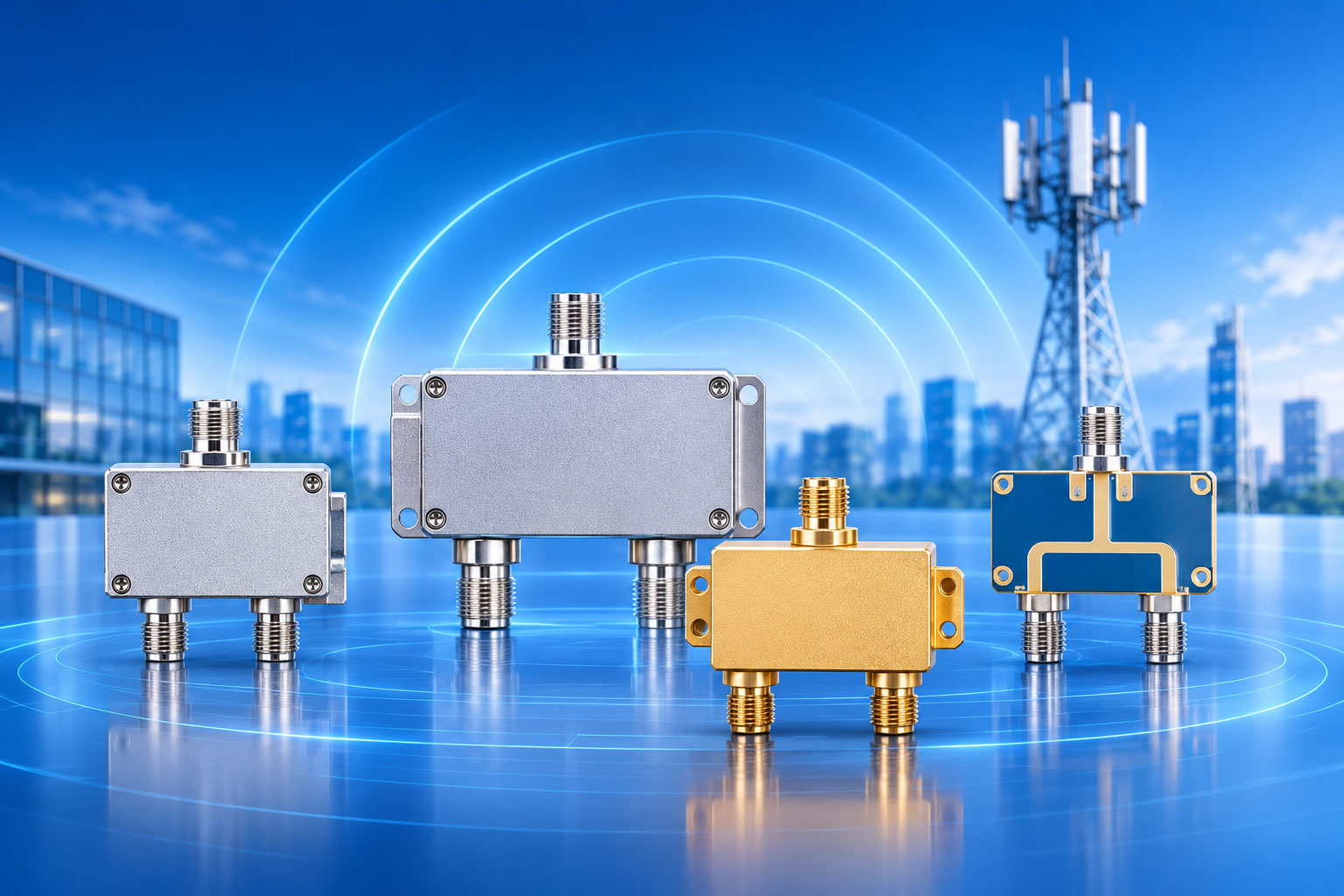
The most common mistake in power splitter selection is treating "2-way splitter" as a single product category and comparing on price. In reality, a 2-way splitter has at least four completely different technology routes, with insertion loss ranging from 0.1dB to 6dB, isolation from 6dB to over 20dB, and power handling from watt-level to 500W-class. Demanding cavity-level performance at microstrip prices, or applying resistive bandwidth to a DAS backbone, is a decision that has already failed at the selection stage.
The four routes each occupy a different engineering zone. Selection is finding the intersection of five constraints: insertion loss, isolation, power, size, and cost.
Start With a Summary Table
|
Dimension
|
Resistive
|
Wilkinson (Microstrip)
|
Cavity
|
Microstrip (Non-Wilkinson)
|
|
2-way insertion loss (incl. 3dB split)
|
6dB
|
3.3–3.5dB (extra 0.3–0.5dB)
|
3.1–3.3dB (extra ≤0.3dB)
|
3.4–3.7dB
|
|
Isolation
|
6dB (equals insertion loss)
|
20dB+ (in-band)
|
Low (no isolation resistor)
|
18–20dB
|
|
Bandwidth
|
DC to mmWave
|
Narrowband mainly (5–15% relative)
|
Wide (octave or more)
|
Medium
|
|
Power handling
|
Very low (watt-level)
|
<100W
|
100–500W+
|
<50W
|
|
PIM
|
N/A (low power)
|
Medium
|
≤-155dBc to -161dBc
|
-140 to -153dBc
|
|
Size
|
Very small
|
Small (PCB area)
|
Large
|
Small
|
|
Cost
|
Very low
|
Low
|
High
|
Low
|
Two numbers in this table stand out: resistive's 6dB insertion loss / 6dB isolation, and cavity's 0.1dB extra insertion loss / 500W power. The space between these two extremes is where Wilkinson and microstrip operate.
Resistive: The Only Splitter That Goes "To DC" — At the Cost of Half the Power
A resistive splitter is essentially a resistor network. A 2-way version uses three 16.7Ω resistors (Z₀/3, 50Ω system) in a symmetrical structure. Insertion loss from input to either output is 6dB, and isolation between any two ports is also 6dB — this is determined by the symmetrical design, not a process limitation.
What does 6dB insertion loss mean? 1W in, each output gets only 250mW. The theoretical split loss takes half (3dB), and the resistor network takes another half. The 3dB extra loss becomes heat entirely. That's why resistive splitter power handling is inherently very low — typically watt-level, with 1W CW being the ceiling for many models.
But resistive has something no other route provides: DC response. With only resistors and no transmission-line resonant structures, it works from DC to mmWave, with no theoretical lower bandwidth limit. Where DC bias and RF signals need to be distributed together, resistive is the only choice.
When is it used in DAS? Basically never. DAS is an AC-coupled RF system with no DC distribution requirement. 6dB insertion loss is an unacceptable waste in a link budget. Resistive belongs in test instruments, CATV branch distribution, and ultra-wideband sweep measurement scenarios.
Wilkinson: High Isolation in a Narrow Band, Bought With One Resistor
The core of a Wilkinson splitter is two quarter-wavelength transmission lines (70.7Ω) plus a 100Ω isolation resistor. The resistor bridges the two output ports. When the two output loads are unbalanced, reflected power is absorbed by the resistor rather than bouncing between the two ports.
This resistor delivers isolation of 20dB or more — an order of magnitude above resistive's 6dB. Meanwhile, the theoretical insertion loss of a Wilkinson is 3dB (2-way), with measured extra loss of 0.3–0.5dB (microstrip implementation), for a total of 3.3–3.5dB. Compared to resistive's 6dB, Wilkinson wastes almost no power in-band.
But the isolation resistor is only effective within the design band. Marki Microwave's application note puts it plainly: outside the specified band, a Wilkinson loses isolation and behaves like a purely reactive splitter — 3dB split loss, no extra loss, but zero isolation between ports. Wilkinson's isolation is bought with bandwidth. A 2-way Wilkinson's relative bandwidth is typically in the 5–15% range; wideband designs require multi-stage cascading, with insertion loss and size both increasing.
When is it used in DAS? Receive paths, low-power distribution, nodes that need port isolation but not high power. Wilkinson's 20dB isolation has value in multi-signal combining or monitoring scenarios — insufficient isolation causes crosstalk between ports. But above 50–100W, the isolation resistor and microstrip line become bottlenecks; both heat dissipation and resistor power dissipation capability fall short.
Cavity: Lowest Insertion Loss, Highest Power — But Isolation Is "Another Matter"
Inside a cavity splitter is a copper rod with stepped diameter changes, using air as the dielectric for impedance transformation. Air's dielectric loss is near zero, and silver-plated conductor surface resistance is extremely low, so extra insertion loss can be held below 0.1dB, for a total 2-way insertion loss of 3.1–3.3dB.
Power handling is cavity's second structural advantage. No PCB dielectric, no isolation resistor, all-metal construction — heat dissipates directly through the metal housing. 100W to 500W average power is cavity's normal range, with high-power models going higher. On PIM, the all-metal air-dielectric structure is inherently better than PCB processes, with ≤-155dBc to -161dBc being normal for cavity splitters.
But there's an engineering fact about cavity that's often overlooked: it has no isolation resistor, so isolation between output ports is low. This is not a defect — it's determined by the structure. A cavity splitter is positioned for power distribution, not power combining. With no isolation between output ports, a reflection at one port directly affects the other. In multi-path combining scenarios, a cavity splitter must be paired with an isolator or circulator — it cannot be directly reverse-used as a combiner.
When is it used in DAS? DAS backbone, source output, high-power distribution nodes. Cavity's 0.1dB extra insertion loss advantage is amplified by cascading in long links — three stages of cavity splitters total 0.3dB extra loss, while three stages of microstrip can eat 1.5dB. That calculation is decisive in a link budget.
Microstrip (Non-Wilkinson): The Lowest-Cost "Good Enough" Option, Bounded by Power and PIM
A microstrip splitter etches conductors onto a dielectric substrate and uses quarter-wavelength lines for impedance transformation. No cavity metal machining cost, no Wilkinson isolation resistor (non-Wilkinson topology), the lowest cost of the four routes, and the smallest size.
The cost is in three places. Insertion loss: microstrip extra loss is 0.4–0.7dB (2-way), total 3.4–3.7dB — 0.3–0.4dB more than cavity. Not much for a single stage, but obvious when cascaded. Power: microstrip splitter power handling is typically below 50W; the dielectric substrate's heat dissipation is limited, and temperature rise at high power causes permittivity drift, further degrading insertion loss. PIM: microstrip PIM is typically in the -140dBc to -153dBc range, clearly below cavity, because of edge exposure in the open microstrip structure and non-linearity in the ground path.
The proper positioning for a microstrip splitter is low-power, short-distance, cost-sensitive, PIM-tolerant edge distribution. Indoor coverage edge nodes, small DAS branches, signal distribution inside test fixtures — in these scenarios, the 0.4dB insertion loss difference can be absorbed by link margin, and the 50W power ceiling is sufficient.
DAS Selection: Eliminate the Impossible First, Then Compare What's Left
Step 1: Look at power.
Above 50W continuous wave, microstrip is out. Above 100W, Wilkinson is out. Cavity remains. If power is below 20W and insertion loss matters, Wilkinson or microstrip can enter the comparison.
Step 2: Look at isolation requirements.
If the splitter also serves as a combiner (reverse use), insufficient port isolation causes crosstalk between channels. Wilkinson's 20dB isolation works in-band; cavity has no isolation resistor, so combining scenarios need an external isolator; resistive's 6dB isolation is essentially meaningless in combining scenarios.
Step 3: Look at cascade depth.
A single-stage splitter's insertion loss difference may be only 0.3dB. But a typical DAS structure is source → first splitter → second splitter → antenna. After three stages of cascading, the insertion loss gap between cavity and microstrip stretches to over 1dB. The deeper the cascade, the more valuable cavity's low insertion loss becomes.
Step 4: Look at temperature and PIM environment.
In outdoor or wide-temperature scenarios, microstrip substrate permittivity drift changes splitter operating characteristics. In multi-operator combining scenarios, microstrip's PIM level can become the bottleneck for uplink noise floor. In both cases, cavity is the more reliable choice.
A Few Specific Numeric Anchors
-
2-way theoretical split loss 3dB, 4-way 6dB, 8-way 9dB. Determined by energy conservation; no technology route can avoid it.
-
Resistive 2-way: insertion loss 6dB, isolation 6dB. The two numbers are equal — a necessary result of the symmetrical structure.
-
Cavity 2-way extra insertion loss ≤0.3dB; three-stage cascade extra total ≤0.9dB.
-
Microstrip 2-way extra insertion loss 0.4–0.7dB; three-stage cascade extra total 1.2–2.1dB.
-
Wilkinson isolation 20dB+ in-band, zero out-of-band. Isolation bandwidth is determined by design band, not a full-band characteristic.