Low PIM RF Directional coupler
1.1 Product introduction
A directional coupler is a low-loss device that accepts one input signal and outputs two signals with the following characteristics in theory.
1. The output amplitudes are not equal.
The output end of the main line is a larger signal, which can basically be regarded as a straight-through, and the output end of the coupling line is a smaller signal. The ratio of the smaller signal on the coupling line to the amplitude of the main line signal is called "coupling" and expressed in dB.
Coupling port power = input power-coupling degree
For example, a 10dB directional coupler, the input power is 30dBm (1W), then the output power of its output end is 30dBm, and the output power of the coupling end is 20dBm. On the surface, it seems to violate the principle of power conservation, but in fact, power is conserved. The misunderstanding is caused by the sometimes unclear conversion between power watts and decibels.
2. The theoretical loss on the main line is determined by the signal level of the coupled line, that is, the degree of coupling.
3. The main line and the coupled line are highly isolated.
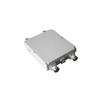
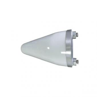
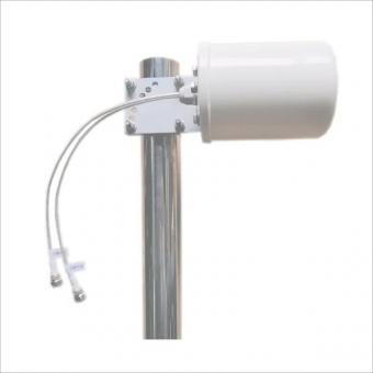
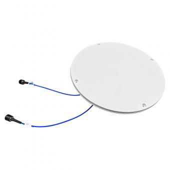
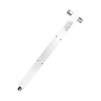
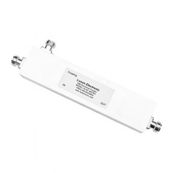
1.2 Appearance of accessories
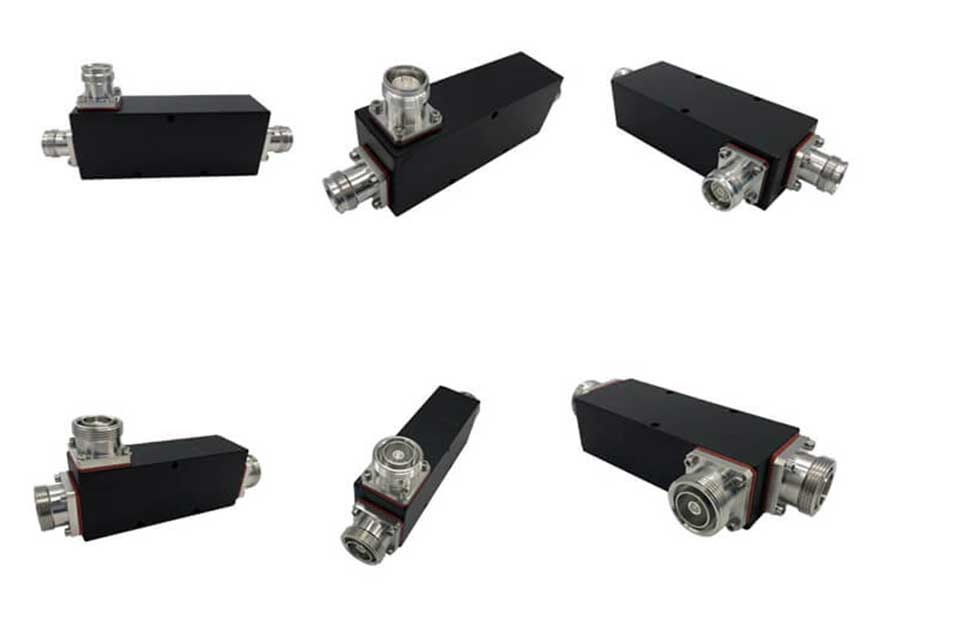
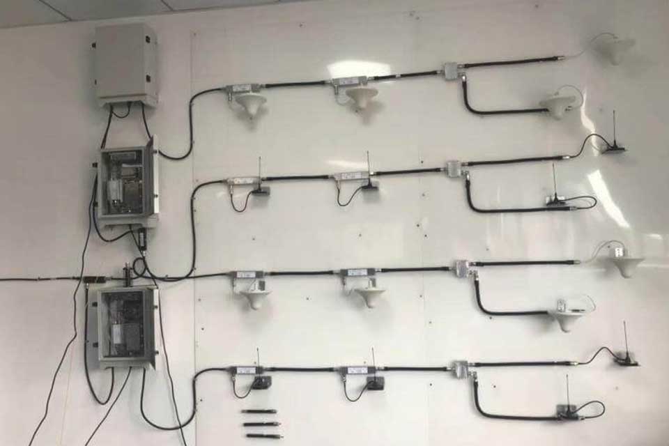
Figure 2 The coupler is distributed in the indoor system
1.3 Technical indicators
The Low PIM Directional provide flat coupling of one signal path to another with directivity (in one direction only) and low VSWR. With the unique design of PIM performance and power handling,
rf Directional couplers offers -161dBc extra low PIM and urtra-wide frequency range (617-4200MHz) covers both public safety and 5G Bands.
|
Model No. |
MNL-DC-XXdB-642-YYF-161dBc (xx refers to coupling value,YY refers to connector type) |
||||||||
|
Freq(MHz) |
617-4200MHz |
||||||||
|
Coupling(dB) |
5dB ±1.2dB |
6dB ±1.2dB |
7dB ±1.2dB |
8dB ±1.3dB |
10dB ±1.4dB |
13dB ±1.4dB |
15dB ±1.5dB |
20dB ±1.5dB |
30dB ±1.8dB |
|
Insertion Loss(dB) |
2.2dB |
1.75dB |
1.4dB |
1.3dB |
1.1dB |
0.7dB |
0.5dB |
0.3dB |
0.3dB |
|
Directivity(dB) |
≥18dB |
≥18dB |
≥18dB |
≥18dB |
≥18dB |
≥18dB |
≥18dB |
≥18dB |
≥15dB |
|
VSWR |
≤1.35 |
||||||||
|
PIM(dBc) |
≤-161dBc@617-2700MHz |
||||||||
|
Average Power |
200W |
||||||||
|
Impedance |
50 ohm |
||||||||
|
Connector |
4.3-10 female,N-Female,or DIN-Female |
||||||||
|
Color |
Black |
||||||||
|
Working Temperaturedeg) |
-35~+65 |
||||||||
|
Application |
Indoor & Outdoor,IP65 |
||||||||
|
Relative Humidity |
5%-95% |
||||||||
1.4 Main application of directional coupler
1. Signal injection
2. Adjustment of signal generator;
3. Monitoring of power flow;
4. Measure incident power and reflected power to determine standing wave ratio;
5. Signal sampling; directional coupler (derives the downlink signal from the base station and sends the uplink signal to the base station)
6. The base station is directly coupled, and a certain proportion of the signal is distributed by the coupler from the receiving and transmitting ports of the base station and sent to the indoor distribution system for signal distribution.

With the 5G is coming, we are also developing 5G-related device products, hoping to develop more and higher-quality products to meet customer needs.
Do you have any questions ?
Call Us : +86 551 65329702